

LEGO Designer:
Grant Passmore (Eiffelman)
Designed: May 2017
Categories:
Support Vehicles and Misc.,
All,
Apollo Program,
Space Agency - NASA
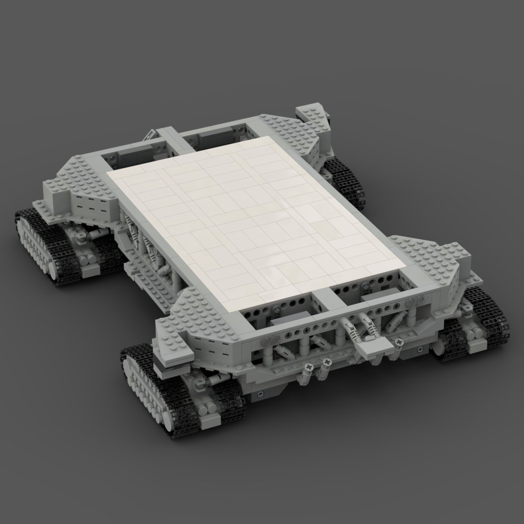
The crawler-transporters, formally known as the Missile Crawler Transporter Facilities, are a pair of tracked vehicles used to transport spacecraft from NASA’s Vehicle Assembly Building (VAB) along the Crawler-way to Launch Complex 39.
They were originally used to transport the Saturn IB and Saturn V rockets during the Apollo, Skylab and Apollo–Soyuz programs. They were then used to transport Space Shuttles from 1981 to 2011. The crawler-transporters carry vehicles on the Mobile Launcher Platform, and after each launch return to the pad to take the platform back to the VAB.
The two crawler-transporters were designed and built by Marion Power Shovel Company using components designed and built by Rockwell International at a cost of US$14 million each. Upon its construction, the crawler-transporter became the largest self-powered land vehicle in the world. While other vehicles such as bucket-wheel excavators like Bagger 293, dragline excavators like Big Muskie and power shovels like The Captain are significantly larger, they are powered by external sources.
The two crawler-transporters were added to the National Register of Historic Places on January 21, 2000.
Designer Notes
The Crawler-Transporter model is strong enough to support the Saturn V.
Exhaust stacks use click hinge connectors to set the angle, I sometimes knock them and have to reposition them. The hinges look better than the alternate fixed pieces which have holes through them.
Picking up the model sometimes moves the side hinged access gangways It is best to pick up the model from the side as the bottom row of the front and back structure have bricks which are only held on by their studs.
The top deck is a tight fit – I had to add the two levers to pop the lid open and one edge is only one plate thick as it was impossible to fit when it was two plates thick. The thin edge goes to the rear of the Crawler.
First time fitting the tracks it can take a few attempts to adjust the length of the hydraulic rams so that the tracks are parallel to the Crawler body. Setting them means fitting and removing the track units a few times (once set there is no issue). Its easier to take off the two 2×2 plates with the ball socket and leave the two side rams attached to the body than try and separate the ball socket connection.
The large hydraulic fluid tank in the middle of the interior is only held by one stud (the second stud just keeps it aligned so that it cannot turn), this has not proven to be an issue as I have inverted the model and it doesn’t fall out (when the top deck is fitted the tank is sandwiched between the floor and top deck and cannot move).
The track are loosly fitted – not to the point where it can come off, but they do sag when the model is picked up. This was done to let the top of the tracks move in a wave and look like they have a lot of weight.
The cross axle’s main purpose is not structural, it connects the track unit to the main body. The load is passed through the flat plates on the top of the unit. Directional stability comes from the four ‘hydraulic rams’ which attach the rack unit to the main body of the crawler.
Downloads
** Updated IO file will load in bricklink **
Further Information and References
Designer Notes
Part count: 2330 bricks, 209 lots.
| Unit | width | length | height |
|---|---|---|---|
| Studs | 50.7 | 38.4 | 9.8 |
| Inches | 16.0 | 12.1 | 3.1 |
| Centimetres | 40.6 | 30.7 | 7.8 |


